गुरुवार, 2 सितंबर 2021

3.5 " TFT LCD shield


#include <MCUFRIEND_kbv.h>

#include <Adafruit_GFX.h>    // Core graphics library


#define LCD_RESET A4 // Can alternately just connect to Arduino's reset pin

#define LCD_CS A3   // Chip Select goes to Analog 3

#define LCD_CD A2  // Command/Data goes to Analog 2

#define LCD_WR A1  // LCD Write goes to Analog 1

#define LCD_RD A0 // LCD Read goes to Analog 0


// Assign human-readable names to some common 16-bit color values:

#define  BLACK   0x0000

#define BLUE    0x001F

#define RED     0xF800

#define GREEN   0x07E0

#define CYAN    0x07FF

#define MAGENTA 0xF81F

#define YELLOW  0xFFE0

#define WHITE   0xFFFF


MCUFRIEND_kbv tft;


void setup() {


 tft.reset();


tft.begin(0x9486); 

tft.setRotation(1);

  tft.fillScreen(RED);

  tft.fillScreen(GREEN);

  tft.fillScreen(BLUE);

  tft.fillScreen(BLACK);

  delay(1000);

  tft.setCursor(80,100);

  tft.setTextColor(WHITE);

  tft.setTextSize(4);

  tft.print("Hello");


  tft.setCursor(220,100);

  tft.setTextColor(RED);

  tft.setTextSize(4);

  tft.print("YouTUBE!");


  tft.fillRect(80,200, 321, 60, RED);


  tft.setCursor(135,215);

  tft.setTextColor(WHITE);

  tft.setTextSize(4);

  tft.print("Subscribe");

  tft.setCursor(40,150);

  tft.setTextColor(WHITE);

  tft.setTextSize(4);

  tft.print("SANI EDU TECHNICAL");


  tft.drawRect(0,0,480,320, RED);

  delay(1000);

}


void loop() {

  tft.fillRect(80,200,321,60,BLACK);

  delay(1000);

  tft.fillRect(80,200,321,60,RED);

  tft.setCursor(135,215);

  tft.setTextColor(WHITE);

  tft.setTextSize(4);

  tft.print("Subscribe");

  delay(1000);

}

शनिवार, 7 अगस्त 2021

RTC (DS1307)with arduino using proteus

 "download  code and circuit"


**circuit**


**more information watch video***

https://youtu.be/dqz9_6AdpjE


**code**

///sani edu technical...

 //please subscribe to my youtube channel

// Date and time functions using a DS1307 RTC connected via I2C and Wire lib

#include <Wire.h>

#include <LiquidCrystal.h>

#include "RTClib.h"


RTC_DS1307 rtc;

LiquidCrystal lcd(7, 6, 5, 4, 3, 2); // (rs, e, d4, d5, d6, d7)


char daysOfTheWeek[7][12] = {"Sun", "Mon", "Tue", "Wed", "Thu", "Fri", "Sat"};


void setup () 

{

  Serial.begin(9600);

  lcd.begin(16, 2);


  if (! rtc.begin()) 

  {

    lcd.print("Couldn't find RTC");

    while (1);

  }


  if (! rtc.isrunning()) 

  {

    lcd.print("RTC is NOT running!");

  }


    rtc.adjust(DateTime(F(__DATE__), F(__TIME__)));//auto update from computer time

    //rtc.adjust(DateTime(2014, 1, 21, 3, 0, 0));// to set the time manualy 


}


void loop () 

{

    DateTime now = rtc.now();


    lcd.setCursor(0, 1);

    lcd.print("TIME ");

    lcd.print(now.hour());

    lcd.print(':');

    lcd.print(now.minute());

    lcd.print(':');

    lcd.print(now.second());

    //lcd.print("   ");

     lcd.print(",");

    lcd.print(daysOfTheWeek[now.dayOfTheWeek()]);

    //lcd.print(" ,");


    lcd.setCursor(0, 0);

    lcd.print("DATE ");


    lcd.print(now.day());

    lcd.print('/');

    lcd.print(now.month());

    lcd.print('/');

    lcd.print(now.year());


}


गुरुवार, 29 जुलाई 2021

How to Add And Simulate Ultrasonic Sensor Library to Proteus

An ultrasonic sensor is an instrument that measures the distance to an object using ultrasonic sound waves.

An ultrasonic sensor uses a transducer to send and receive ultrasonic pulses that relay back information about an object’s proximity.  


 download ckt and code..

ckt.


watch video for more information..


code..

// defines pins numbers

const int trigPin = 9;

const int echoPin = 10;


// defines variables

long duration;

long distance;


void setup() {

pinMode(trigPin, OUTPUT); // Sets the trigPin as an Output

pinMode(echoPin, INPUT); // Sets the echoPin as an Input

Serial.begin(9600); // Starts the serial communication

}


void loop() {

// Clears the trigPin

digitalWrite(trigPin, LOW);

delayMicroseconds(2);


// Sets the trigPin on HIGH state for 10 micro seconds

digitalWrite(trigPin, HIGH);

delayMicroseconds(10);

digitalWrite(trigPin, LOW);


// Reads the echoPin, returns the sound wave travel time in microseconds

duration = pulseIn(echoPin, HIGH);


// Calculating the distance

distance= duration*0.034/2;


  Serial.print(distance);

  Serial.println("  CM ");

}

LCD 16x2 scrolling text display with Arduino in Poteus....

 download ckt and code...

#include <LiquidCrystal.h>

const int rs = 12, en = 11, d4 = 5, d5 = 4, d6 = 3, d7 = 2;

LiquidCrystal lcd(rs, en, d4, d5, d6, d7);


void setup() {

  lcd.begin(16, 2);

 }


void loop() {

  lcd.clear();

  lcd.setCursor(2, 0);

   lcd.print("SANI EDU TECH");

  for (int i = 0; i < 13; i++) {

   lcd.scrollDisplayLeft();

   delay(200); 


     }

}


watch video..


रविवार, 25 जुलाई 2021

Bidirectional Visitor Counter with Light Control using Arduino

 download  code and circuit....

#include <Wire.h>

#include <LiquidCrystal.h>


LiquidCrystal lcd(6,5,4,3,2,1);

 #define inSensor 7

#define outSensor 8


int inStatus;

int outStatus;


int countin = 0;

int countout = 0;


int in;

int out;

int now;


#define relay 9

void setup() {

 lcd.begin(16,2);

  pinMode(inSensor, INPUT);

  pinMode(outSensor, INPUT);

  pinMode(relay, OUTPUT);

  digitalWrite(relay, LOW);

 lcd.setCursor(0,0); // put your setup code here, to run once:

lcd.print("Visitor counter");

delay(1000);


}


void loop() {

   inStatus =  digitalRead(inSensor);

  outStatus = digitalRead(outSensor);

  if (inStatus == 1)

  {

    in = countin++;

  }


  if (outStatus == 1)

  {

    out = countout++;

  }


  now = in - out;


  if (now <= 0)

  {

    digitalWrite(relay, LOW);

    lcd.clear();

     lcd.setCursor(0,0); // put your setup code here, to run once:


    lcd.print("No Visitor");

    lcd.setCursor(0,1);

    lcd.print("Light Off");

    delay(500);

  }

  else

  {

    digitalWrite(relay, HIGH);


   lcd.clear();

     lcd.setCursor(0,0);

    lcd.print("Current Visitor");


    lcd.print(now);


   lcd.setCursor(0,1);

    lcd.print("IN: ");

    lcd.print(in);


   lcd.setCursor(8,1);

    lcd.print("OUT: ");

    lcd.print(out);


    delay(500);

  }

       }


शनिवार, 10 अप्रैल 2021

keypad interfacing with arduino.

 *** download circuit diagram and complete keypad (4*3) interfacing code.***

1. circuit diagram ......


2.**** for more information watch video ****


3. *******complete code ******* by sani edu technical*****

// Including LCD library

#include<LiquidCrystal.h>


// Setting (RS,E,D4,D5,D6,D7) for particular pin number

LiquidCrystal lcd(6, 5, 4, 3, 2, 1);


int c1 = 11, c2 = 12, c3 = 13;

int r1 = 10, r2 = 9, r3 = 8, r4 = 7;

int del = 600;


void setup() {

  lcd.begin(16, 2);

  lcd.setCursor(0, 0);

  lcd.print("Hello !");

  delay(1000);

  lcd.clear();


  /* use input pull-up  *//


  */

  pinMode(c1, INPUT_PULLUP);

  pinMode(c2, INPUT_PULLUP);

  pinMode(c3, INPUT_PULLUP);


  // Set r1,r2,r3,r4 pins to OUTPUT mode

  pinMode(r1, OUTPUT);

  pinMode(r2, OUTPUT);

  pinMode(r3, OUTPUT);

  pinMode(r4, OUTPUT);

}


void loop() {

 row1();

  row2();

  row3();

  row4();

}


void row1() {

 digitalWrite(r1, LOW);

  digitalWrite(r2, HIGH);

  digitalWrite(r3, HIGH);

  digitalWrite(r4, HIGH);


  if (digitalRead(c1) == LOW) {   //print 1,2,3

    lcd.print("1"); delay(del);

  }

  else if (digitalRead(c2) == LOW) {

    lcd.print("2"); delay(del);

  }

  else if (digitalRead(c3) == LOW) {

    lcd.print("3"); delay(del);

  }

}


void row2() {

  digitalWrite(r1, HIGH);

  digitalWrite(r2, LOW);

  digitalWrite(r3, HIGH);

  digitalWrite(r4, HIGH);


  if (digitalRead(c1) == LOW) {    //print 4,5.6

    lcd.print("4"); delay(del);

  }

  else if (digitalRead(c2) == LOW) {

    lcd.print("5"); delay(del);

  }

  else if (digitalRead(c3) == LOW) {

    lcd.print("6"); delay(del);

  }

}


void row3() {

  digitalWrite(r1, HIGH);

  digitalWrite(r2, HIGH);

  digitalWrite(r3, LOW);

digitalWrite(r4, HIGH);


  if (digitalRead(c1) == LOW) {    ///print 7,8,9

    lcd.print("7"); delay(del);

  }

  else if (digitalRead(c2) == LOW) {

    lcd.print("8"); delay(del);

  }

  else if (digitalRead(c3) == LOW) {

    lcd.print("9"); delay(del);

  }

}


void row4() {

  digitalWrite(r1, HIGH);

  digitalWrite(r2, HIGH);

  digitalWrite(r3, HIGH);

  digitalWrite(r4, LOW);


  if (digitalRead(c1) == LOW) {   ///print *,0,#

    lcd.print("*"); delay(del);

  }

  else if (digitalRead(c2) == LOW) {

    lcd.print("0"); delay(del);

  }

  else if (digitalRead(c3) == LOW) {

    lcd.print("#"); delay(del);

  }

}


गुरुवार, 8 अप्रैल 2021

arduino based voice control home automation ..

 download circuit and code and android app....
1. voice control android app link-https://drive.google.com/drive/folders/1JsOYFbFTBohRFdC0Ins6f8khoelZj6Ce?usp=sharing
2. circuit diagram-


4. watch video for more details..


5. download code complete code..


String voice ;
void setup() {
  // put your setup code here, to run once:
Serial.begin(9600);
pinMode(12, OUTPUT);
pinMode(11, OUTPUT);
}

void loop() {
  // put your main code here, to run repeatedly:
while(Serial.available()){
  delay(3);
  char c = Serial.read();
  voice+=c;
}

if(voice.length() >0)
{
  Serial.println(voice);
  if(voice == "turn on LED")
  {
  digitalWrite(12, HIGH);
  }
 else if(voice == "turn off LED")
  {
  digitalWrite(12, LOW);
  }
   else if(voice == "turn on fan")
  {
  digitalWrite(11, HIGH);
  }
   else if(voice == "turn off fan")
  {
  digitalWrite(11, LOW);
  }
  voice = "";
}

}


plz like and share this tutorial.

गुरुवार, 25 मार्च 2021

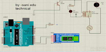
Arduino based home automation using Bluetooth...

 download circuit ,arduino code and app.

1. circuit connection.


2. video link....


3. code for arduino....

int led=13;

void setup() {

 pinMode(led,OUTPUT);

  Serial.begin(9600);  

// put your setup code here, to run once:

}

void loop() {

 /// char ab ;

 if (Serial.available ())

 { 

 // put your main code here, to run repeatedly:

 char  ab=Serial.read();

 Serial.print(ab);

 if ( ab =='a')

{

  digitalWrite( led, HIGH);


}   

 if ( ab=='b' )

{

 digitalWrite( led, LOW); 

}

}

}
4. mit appp ...download app.

https://drive.google.com/file/d/1rRTlQ1itMfSMpt0AWZJoQ0vqa_6H6-JX/view

शनिवार, 20 मार्च 2021

What is a transistor and how does it work/ ट्रांजिस्टर क्या है और यह कैसे काम करता है?

 transistor(ट्रांजिस्टर)एक ट्रांजिस्टर एक अर्धचालक उपकरण है जिसका उपयोग इलेक्ट्रॉनिक संकेतों और विद्युत शक्ति को बढ़ाने या स्विच करने के लिए किया जाता है। ट्रांजिस्टर आधुनिक इलेक्ट्रॉनिक्स के बुनियादी भवन ब्लॉकों में से एक हैं। यह अर्धचालक सामग्री से बना होता है जो आमतौर पर बाहरी सर्किट से जुड़ने के लिए कम से कम तीन टर्मिनलों के साथ होता है।

1. पहला टर्मिनल एमिटर होता ह। जीस से करंट एमिट होता या आप बोल सकते ह करंट इंटर होता ह।

2 . दूसरा टर्मिनल बेस होता ह। जो एमिटर to कलेक्टर करंट फलो को कॉन्ट्रोल करता ह।

3. तीसरा टर्मिनल कलेक्टर होता ह। जिस से करंट कलेक्ट करते ह। य आप बोल सकते ह करंट आउटपुट करता ह।

-ट्रांजिस्टर दो प्रकार के होते ह।

1 . npn ट्रांजिस्टर।

2. pnp ट्रांजिस्टर।

- npn ट्रांजिस्टर मे करंट डायरेक्शन बहार की ऒर होता .जो आप निचे दिए गए फोटो में देख सकते ह। npn ट्रांजिस्टर मे base पे पॉजिटिव सप्लाई देने से एमिटर to कलेक्टर पे current flow होता ह।

- pnp ट्रांजिस्टर मे करंट डायरेक्शन अंदर की ऒर होता .जो आप निचे दिए गए फोटो में देख सकते ह। npn ट्रांजिस्टर मे base पे निगेटिव सप्लाई देने से एमिटर to कलेक्टर पे current flow होता ह।

- कैसे काम करता ह ट्रांजिस्टर जाने के लिए निचे दिए गए विडिओ को आप देख सकते ह।

-अगर आपको मेरे बताए गए ट्रिक्स आपको अच्छा लगे तो। आप कमेंट करना न भूले।

मंगलवार, 16 मार्च 2021

HC-05 Bluetooth Module with Arduino-MIT App Inventor..

 आज हम इस टिटोरियल में सीखे गए बुलेटूथ मॉडुल (HC-05 Bluetooth Module with Arduino-MIT App)
को कैसे कनेक्ट करते ह। 
कॉम्पोनेन्ट लिस्ट नीचे दिया गया ह। 

-arduino uno ,

-buletooth  module ,

-led 

-थोड़ा connector ,

-एक मोबाइल android 

निचे विडिओ लिंक दिया हुआ ह उसके मदद से आप connenation कर सकते ह। 

https://youtu.be/CoBSyhI7Yi4


नोट -mit app download link

code-for arduino uno-

/*  

HC05 - Bluetooth AT-Command mode 

*/

#include <SoftwareSerial.h>

SoftwareSerial MyBlue(6, 7); // RX | TX

int flag = 0;

int LED = 8;

void setup()

{  

  Serial.begin(9600);

  MyBlue.begin(9600);

  pinMode(LED, OUTPUT);

  Serial.println("Ready to connect\nDefualt password is 1234 or 000");

}

void loop()

{

   if( MyBlue.available()>0){

    // read the bluetoot data and store it

  flag = MyBlue.read();

    char Rec = char(flag);

    if (Rec != '0')

    {

    Serial.println(Rec);

    } 

  }

  if (flag == 'a')

  {

    digitalWrite(LED, HIGH);

    Serial.println("LED On");

  }

  if (flag == 'b')

  {

    digitalWrite(LED, LOW);

    Serial.println("LED Off");

  }

}


रविवार, 14 मार्च 2021

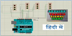
Arduino Traffic Light Tutorial.

 आप यहा सर्किट and code  डाउनलोड  कर सकते ह .

1.  आप सर्किट डेटलेस देख़ सकते ह। 


२.  निचे दिए गए विडिओ से आप असानी से ट्रैफ़िक लाइट बनाना सीख सकते ह। 

३. यहा पर आपको ट्रैफिक लाइट का code दिया हुआ ह।  

int g1=13;
int dp=1000;
int g2=12;
int g3=11;
int g4=10;
int y1=9;
int y2=8;
int y3=7;
int y4=6;
int r1=5;
int r2=4;
int r3=3;
int r4=2;


void setup() {
   pinMode( g1, OUTPUT); 
  pinMode( g2, OUTPUT); 
 pinMode( g3, OUTPUT);     
 pinMode( g4, OUTPUT);
 pinMode( y1, OUTPUT);
 pinMode( y2, OUTPUT);
 pinMode( y3, OUTPUT);
 pinMode( y4, OUTPUT);
 pinMode( r1, OUTPUT);
pinMode( r2, OUTPUT);
 pinMode( r3, OUTPUT);
 pinMode( r4, OUTPUT);// put your setup code here, to run once:

}

void loop() {
digitalWrite ( y1 , HIGH);
delay(dp);
digitalWrite ( y1 , LOW);
  north();
  delay(5000); 
  digitalWrite ( y2 , HIGH);
  delay(dp);
   digitalWrite ( y2 , LOW);
  south();
   delay(5000);
    digitalWrite ( y3 , HIGH);
    delay(dp);
     digitalWrite ( y3 , LOW);
  est();
   delay(5000);
   digitalWrite ( y4 , HIGH);
   delay(dp);
   digitalWrite ( y4 , LOW);
  west();
   delay(5000);
}

void  north() 
{
 digitalWrite ( g1 , HIGH);
 digitalWrite ( g2 , LOW);
 digitalWrite ( g3 , LOW);
 digitalWrite ( g4 , LOW);
 digitalWrite ( r1 , LOW);
 digitalWrite ( r2 , HIGH);
  digitalWrite ( r3 , HIGH);
   digitalWrite ( r4 , HIGH);
}
 
void south()
{
 digitalWrite ( g2 , HIGH);
 digitalWrite ( g3 , LOW);
 digitalWrite ( g4 , LOW);
 digitalWrite ( g1 , LOW);
 
digitalWrite ( r1 , HIGH);
 digitalWrite ( r2 , LOW);
  digitalWrite ( r3 , HIGH);
   digitalWrite ( r4 , HIGH);

}
void  est() 
{
 digitalWrite ( g3 , HIGH);
 digitalWrite ( g1 , LOW);
 digitalWrite ( g2 , LOW);
 digitalWrite ( g4 , LOW);

digitalWrite ( r1 , HIGH);
 digitalWrite ( r2 , HIGH);
  digitalWrite ( r3 , LOW);
   digitalWrite ( r4 , HIGH);
}
void  west()
{
 digitalWrite ( g4 , HIGH);
 digitalWrite ( g1 , LOW);
 digitalWrite ( g2 , LOW);
 digitalWrite ( g3 , LOW);


digitalWrite ( r1 , HIGH);
 digitalWrite ( r2 , HIGH);
  digitalWrite ( r3 , HIGH);
   digitalWrite ( r4 , LOW);
 
 
}  


   note -g -ग्रीन लाइट ,r -रेड लाइट , y -येलो लाइट।

गुरुवार, 4 मार्च 2021

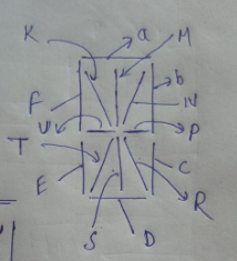
Fourteen-segment display interface


A fourteen - segment  display is a type of display based on 14 segments that can be turned on or off to produce
letters and numbers.


    14 segment display name in proteus...


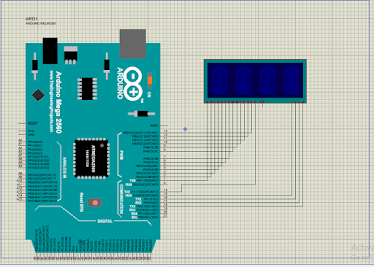
4 digit  14 segment display name in proteus.


complete circuit diagram ....


complete code for$ digit  Fourteen-segment display  interface....


 int a=1; int b=2; int c=3; int d=4; int e=5; int f=6; int k=7; int m=8; int n=9; int p=10;

int r=11; int s=12; int t=13; int u=14; int e1=15;int e2=16; int e3=17; int e4=18; 

void setup() {
  // put your setup code here, to run once:
pinMode( a,OUTPUT);
pinMode( b,OUTPUT);
pinMode( c,OUTPUT);
pinMode( d,OUTPUT);
pinMode( e,OUTPUT);
pinMode( f,OUTPUT);
pinMode( k,OUTPUT);
pinMode( m,OUTPUT);
pinMode( n,OUTPUT);
pinMode( p,OUTPUT);
pinMode( r,OUTPUT);
pinMode( s,OUTPUT);
pinMode( t,OUTPUT);
pinMode( u,OUTPUT);
pinMode( e1,OUTPUT);
pinMode( e2,OUTPUT);
pinMode( e3,OUTPUT);
pinMode( e4,OUTPUT);
}

void loop() {
     // exm print (SANI)

// for (S)    
digitalWrite( a,1);
digitalWrite( b,0);
digitalWrite( c,1);
digitalWrite( d,1);
digitalWrite( e,0);
digitalWrite( f,1);
digitalWrite( k,0);
digitalWrite( m,0);
digitalWrite( n,0);
digitalWrite( p,1);
digitalWrite( r,0);
digitalWrite( s,0);
digitalWrite( t,0);
digitalWrite( u,1);
digitalWrite( e1,0);
digitalWrite( e2,1);
digitalWrite( e3,1);
digitalWrite( e4,1);
delay(50);
digitalWrite( a,1);
digitalWrite( b,1); ///for (A)
digitalWrite( c,1);
digitalWrite( d,0);
digitalWrite( e,1);
digitalWrite( f,1);
digitalWrite( k,0);
digitalWrite( m,0);
digitalWrite( n,0);
digitalWrite( p,1);
digitalWrite( r,0);
digitalWrite( s,0);
digitalWrite( t,0);
digitalWrite( u,1);
digitalWrite( e1,1);
digitalWrite( e2,0);
digitalWrite( e3,1);
digitalWrite( e4,1);
delay(50);  ///for (N)
digitalWrite( a,0);
digitalWrite( b,1);
digitalWrite( c,1);
digitalWrite( d,0);
digitalWrite( e,1);
digitalWrite( f,1);
digitalWrite( k,1);
digitalWrite( m,0);
digitalWrite( n,0);
digitalWrite( p,0);
digitalWrite( r,1);
digitalWrite( s,0);
digitalWrite( t,0);
digitalWrite( u,0);
digitalWrite( e1,1);
digitalWrite( e2,1);
digitalWrite( e3,0);
digitalWrite( e4,1);
delay(50);

digitalWrite( a,1); ////for (I);
digitalWrite( b,0);
digitalWrite( c,0);
digitalWrite( d,1);
digitalWrite( e,0);
digitalWrite( f,0);
digitalWrite( k,0);
digitalWrite( m,1);
digitalWrite( n,0);
digitalWrite( p,0);
digitalWrite( r,0);
digitalWrite( s,1);
digitalWrite( t,0);
digitalWrite( u,0);
digitalWrite( e1,1);
digitalWrite( e2,1);
digitalWrite( e3,1);
digitalWrite( e4,0);
delay(50);
}

गुरुवार, 31 दिसंबर 2020

Free SCADA Software Download.....

 What is Scada software?

Supervisory control and data acquisition (SCADA) is a system of software and hardware elements that allows industrial organizations to: ... Monitor, gather, and process real-time data. Directly interact with devices such as sensors, valves, pumps, motors, and more through human-machine interface (HMI) software.


  1. click here to download
  1. click here to download-https://drive.google.com/file/d/10LFraYnFUbORgIeAFB8Ns-dqClUXB2HH/view?usp=sharing
  1. installation process video link


बुधवार, 30 दिसंबर 2020

free plc programming software download

 what is PLC.

A Programmable Logic Controller, or PLC, is a ruggedized computer used for industrial automation. These controllers can automate a specific process, machine function, or even an entire production line.

How does a PLC work?

The PLC receives information from connected sensors or input devices, processes the data, and triggers outputs based on pre-programmed parameters.
Depending on the inputs and outputs, a PLC can monitor and record run-time data such as machine productivity or operating temperature, automatically start and stop processes, generate alarms if a machine malfunctions, and more. Programmable Logic Controllers are a flexible and robust control solution, adaptable to almost any application.


1. Click here to download PLC software 

https://youtu.be/5SeEI-6oT10

https://drive.google.com/file/d/1f7YjERw40lJ-fSN13lcW13maJ80FQXSq/view?usp=sharing


3.5 " TFT LCD shield

                                                                                                                                            ...